
Description
Overview
Overview
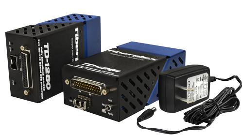
The TD-1280 and TD-1281 pair together to form a powerful balanced serial data transport solution. The DB-25 connectors are pinned out to directly support a TIA-232 serial link. However due to the transparency and flexibility of the design, the TD-1280/81 can be used as 3×2 independent 1 Mbps TIA-232 channels and 5×5 independent 120 Kbps TIA-232 channels.
This incredible versatility can solve a myriad of serial data communications problems. Your once limited serial links can not only be consolidated but extended to over 20 Km on a single fiber pair. SCADA (supervisory control and data acquisition), Telecommunications, Facility Automation and Control can all benefit from the TD-1280/81.
For more advanced systems, a ‘Regeneration’ switch on the TD-1281 allows users to toggle between synchronous applications that require Send Timing (ST) and asynchronous or synchronous applications that require Terminal Timing (TT).
How do we get so many channels?
By using a technology unique to FiberPlex products called ‘transparency’, we are able to use all the clock, data and control channels of the standard EIA-530 interface completely independently of one another. This provides the ability to have (2) bi-directional 1 Mbps TIA-232 serial with (1) unidirectional 1 Mbps TIA-232 and (5) bi-directional 120 Kbps TIA-232, or even independently as (3) 1 Mbps TIA-232 in one direction and (2) in the other [3×2] and (5) 120 Kbps TIA-232 in one direction and (5) in the other [5×5]. The table below shows how these channels are pinned out.
| PINOUTS | |||||
| Pin | TD-1281 (To DCE) Direction | TD-1280 (To DTE) Direction | Individual TX/RX channels | TIA-232 | |
| Function | |||||
| 1 | Chassis Ground | Chassis Ground | |||
| 2 | Out | In | 1 Mbps TIA-232 | TX | Send Data (SD) |
| 3 | In | Out | RX | Receive Data (RD) | |
| 4 | Out | In | 120 Kbps TIA-232 | TX | Request To Send (RTS) |
| 5 | In | Out | RX | Clear To Send (CTS) | |
| 6 | In | Out | RX | Data Set Ready (DSR) | |
| 7 | Signal Ground | Signal Ground | |||
| 8 | In | Out | 120 Kbps TIA-232 | RX | Receiver Ready (RR) |
| 9 | |||||
| 10 | |||||
| 11 | |||||
| 12 | |||||
| 13 | |||||
| 14 | Out | In | 120 Kbps TIA-232 | TX | Secondary Send Data (S-SD) |
| 15 | In | Out | Â 1Mbps TIA-232 | RX | Send Timing (ST) |
| 16 | |||||
| 17 | In | Out | 1 Mbps TIA-232 | RX | Receive Timing (RT) |
| 18 | Out | In | 120 Kbps TIA-232 | TX | Local Loopback (LL) |
| 19 | Out | In | TX | Secondary Request To Send (S-RTS) | |
| 20 | Out | In | TX | Terminal Ready (TR) | |
| 21 | |||||
| 22 | In | Out | 120 Kbps TIA-232 | RX | Ring Indicator (RI) |
| 23 | |||||
| 24 | Out | In | 1 Mbps TIA-232 | TX | Terminal Timing (TT) |
| 25 | In | Out | 120 Kbps TIA-232 | RX | Test Mode (TM) |
| Data and clock signals (highlighted) have a maximum data rate of 1 Mbps. All other signals not highlighted are control signals with a maximum data rate of 120 Kbps. | |||||
Typical Applications


Reviews
There are no reviews yet.