Loading...

Artel FL-ST2110-SFP/2CH

Category: Tags: , , , ,

$2,047.10

Description

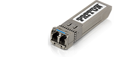
The Artel FL-ST2110-SFP is an SDI Video to ST2110 Gateway.  The SFP Module can plug into Video Gear equipped with SDI Host SFP Slots and it will encapsulate or de-encapsulate the SDI data to and from IP using SMPTE ST2110 or ST2022-6.

Video SFPs improve how broadcast equipment is inter-connected and it has been widely adopted.  SFP cages enable multi-format inputs and outputs without needing a separate box for each interface or cable type (coax, single-mode, multimode etc.).  The broadcast industry adapted the MSA standard and adapted it for use with SDI based video signals, rather than IP data.  This was harkening towards convergence with the world of Ethernet/IP.

Now, the Media Broadcast and Production market is rapidly moving to Ethernet/IP for switching and transport.  This video SFP module helps deliver IP Convergence in Media Broadcast.

The unit is designed to interface with video source and destination devices (via SFP) that are not yet ST2110 IP native, enabling those devices to exist on an IP network.  Since the FL-ST2110-SFP plugs directly into SDI SFP/SFP+ cages, the solution dramatically simplifies the migration and integration of SMPTE2110 IP and SDI equipment.

The SFP form factor offers a compact, lightweight, high-density SDI-to-IP gateway solution that is pre-integrated with Artel Video Broadcast portfolios and easily configured for use with any brand of video gear.

Unit options include encapsulation/encoding and de-encapsulation/decoding using ST2110 or ST2022-6.  MSA-compliant versions support a single channel only.  Non-MSA units operate with either a single or dual channel.  Units can be installed at device locations to provide for the desired mix of input and output connectivity over the IP network.  Designed to support SDI video pathological signals over IP, the module can ensure the quality of video transmission.

FL-ST2110-SFP utilizes SMPTE for all essences: Video according to ST 2110-20 (single or dual channel), Audio according to ST 2110-30 (PCM), Ancillary Data according to ST 2110-40 and Video/Audio/Ancillary according to ST 2022-6.

Supports Seamless Protection Switching of RTP Datagrams according to ST 2202-7 multiplexed over one physical interface.  Traffic Shaping is performed in accordance with ST 2110-21.  For Control and Management the unit offers NMOS including IS-04 v1.2 (Discovery), IS-05 v1.0 (Routing), IS-08 v1.0 (Audio Mapping), IS-09 (System), BCP-002-01 (Essence Grouping), TR-1001 (System Environment and device behaviors) as well as Ember+ and Ember+ Bess Protocol.

Clean Switch and Frame Sync. features can be added and enabled with optional licenses.

The “Clean Switch” feature allows switching between different video sources (e.g., cameras, players) without  any visible or audible artifacts that otherwise happen during the transition.  Clean Switch ensures the source switching it done without glitches, flashes, or color changes or audio “pops” during the video switch.

Clean switching can be applied to just the video switching, or extended to include to essences (video, audio and ancillary).  The feature is functional when switching between ST2110-20 to ST2110-20 (uncompressed) or between ST2110-22 to ST2110-22 type of essences.

The units offer native PTP synchronization support according to ST 2110-10 (AES-R16-2016).  When the SFP is being used as an Encapsulator, it offers the option to add “Frame Sync. feature, if PTP frame syncing at the source is desirable.

The module is particularly useful with…

  • HD Camera and Monitor Systems.
  • Broadcast Video Transmission.
  • Video Matrix Switchers
  • Converters, Encoder & Decoders


Applications
The Fiberlink ST2110 SFP is an HD/3G-SDI to SMPTE ST2110 SFP that is simple to install into a camera or monitor with available SFP ports.  The device allows the user to deploy an IP infrastructure using standard off-the-shelf IP switches and cables to transport your SDI signal as an IP stream between the source and display.  The unit offers ST2022-7 hitless switching capabilities and configurable encapsulation and de-encapsulation capabilities in a single unit.  The FL-ST2110-SFP requires PTP Synchronization which can be configured via the included RestAPI.  Available with either the MSA pinout for single stream or non-MSA pinout for single or dual stream capabilities.


The unit is also offered as an ST2022-6 SFP for HD/3G-SDI to SMPTE ST2022-6.  The version also offers user configurable encapsulation or de-encapsulation capabilities and both MSA pinout for single stream and non-MSA pinout for single or dual stream capabilities.

  • SDI Host SFP – This SFP module installs in standard SDI Host SFP transmitting video signals used in broadcast video equipment.
  • SMPTE 2110 Encode & Decode – The module Encapsulates and De-Encapsulates SDI Signals on host side over Ethernet/IP using the ST2110 or ST2022-6 standard.
  • SDI Formats to 3G – The device auto-senses of HD-SDI to 3G-SDI formats.
  • Single or Dual Channel – The MSA pinout only accommodates single channel operation. A non-MSA compliant SFP supports single or dual channel operation
  • Interoperable – IP and SMPTE standard-based implementation provides for interoperability with existing IP networks and SMPTE device integrations.
  • Modular & Miniature – The SFP pluggable form factor enables high availability, reduced points of failure, and easy maintenance operations. Installed inside existing ethernet switch footprints.
  • Cost Savings – Enables deployments using less equipment, fewer cables, and lower power consumption.
  • Monitoring – Simple device configuration and monitoring is performed using I2C via a serial interface for alarms, voltage and temperature.
  • Standards-based – Follows SMPTE for all essences. Video according to ST 2110-20 (single or dual channel), Audio according to ST 2110-30 (PCM), Ancillary Data according to ST 2110-40 and Video/Audio/Ancillary according to ST 2022-6.
  • PTP Synchronization – Native PTP support according to ST 2110-10 (AES-R16-2016).
  • Redundancy – Supports Seamless Protection Switching of RTP Datagrams according to ST 2202-7 multiplexed over one physical interface.
  • Traffic Shaping – Following ST 2110-21 ensures reliable and predictable video delivery over IP with video streams delivered in time and sequence.
  • NMOS Support – Follows the Networked Media Open Specification for Control and Management including IS-04 v1.2 (Discovery), IS-05 v1.0 (Routing), IS-08 v1.0 (Audio Mapping), IS-09 (System), BCP-002-01 (Essence Grouping), TR-1001 (System Environment and device behaviors) as well as Ember+ and Ember+ Bess Protocol.
  • Clean Switching – A special “Clean Switch” feature ensures source switching it done without glitches, flashes, or color changes or audio “pops” during the video switch.
  • Software Upgrades – Devices are software upgradeable to adapt to new standards, adapting to new protocols.

SFP Pin Description: Pin-Out table.

PIN # NAME FUNCTION NOTES
1 VEE Ground
2 TX_FAULT Transmitter fault Transmitter fault indicator (Active high, open drain)
3 TX_DIS Transmitter disable TX_DIS is an active high input that is used to shut down the transmitted signal. It is internally pulled up with a 4.7k to 10k resistor. High/Open = Transmitted signal disabled (See programmed option for more details)
4 SDA Serial Data Must be pulled up to VCC (4.7k-10k) on the host board (open drain)
5 SCL Serial Clock Must be pulled up to VCC (4.7k-10k) on the host board (open drain)
6 MOD_ABS Module Absent Connected to VEE in the module
7 RS0 Rate Select 0 Floating, Internally Not Connected
8 RX_LOS Loss of Signal RX_LOS is an active high open-drain output that returns the loss of a valid optical signal by the receiver or the loss of a valid received data. High = No optical signal or received data invalid (See programmed option for more details)
9 RS1 Rate Select 1 Floating, Internally Not Connected
10 VEE Ground
11 VEE Ground
12 RD- Inv. Received Data RD± are the differential receiver outputs. The AC coupling is done inside the module and is thus not required on the host board.
13 RS+ Received Data
14 VEE Ground
15 VCC +3.3V Supply Defined as 3.3V±5% at the SFP connector pin. Recommended host board power filtering is shown in figure section 6.
16 VCC +3.3V Supply
17 VEE Ground
18 TD+ Transmit Data In TD± are the differential inputs of the transmitter. They are AC coupled differential lines with 100 ohms differential termination inside the module.
19 TD- Inv. Transmit Data In
20 VEE Ground

Absolute Maximum Ratings: Exceeding any of these ratings may permanently damage the module. Exposure to absolute maximum rating conditions for extended periods may affect device reliability.

SYMBOL MIN MAX UNIT NOTES
Supply Voltage VCC_MAX 0 3.6 V
Operating Case Temperature* TC_MAX 0 +70 C
Storage Temperature TS -40 +85 C
Operating Relative Humidity 5 95 % Non-condensing
ESD Rating 1 kV HBM
*Measured on the top side of the module in the center.

Recommended Operating Conditions: Unless otherwise specified, all specifications are valid under these conditions: VCC = 3.3 ± 5%, TC=0C to +70C. Specifications are guaranteed by design and characterization.

SYMBOL MIN TYP MAX UNIT NOTES
Supply Voltage VCC 3.135 3.3 3.465 V
Operating Case Temperature* TC 0 +70 C Note 1
Host Serial Data Rate SD BRSD 270 Mbps ST259, Note 2
Host Serial Data Rate HD BRHD 1483, 1485 Mbps ST292, Note 2
Host Serial Data Rate 3G BR3G 2967, 2970 Mbps ST424, Note 2
Host Serial Data Rate UHD 5934, 5940, 11868, 11880 Mbps ST2081, ST2082, Note 2
10GbE Data Rate BR10GE 10.3125 Gbps IEEE 802.3ae, ±100ppm
Distance OM1 33 m IEEE 802.3ae
Distance OM2 82 m IEEE 802.3ae
Distance OM3 300 m IEEE 802.3ae
Distance OM4 400 m IEEE 802.3ae
Note 1: Measured on the top side of the module in the center.
Note 2: Host interface supported rate will depend on the programmed features

DC Characteristics:

SYMBOL MAX UNIT NOTES
Power Supply Current ICC 606 mA Note 1, 2
Total Power Consumption PD 2000 mA Note 1, 2
Note 1: All power consumption characterized at 25C, Vcc = 3.3V.
Note 2: Power consumption will depend on the programmed option

Digital IO Characteristics:

SYMBOL MIN MAX UNIT NOTES
TX_DIS (Input)
Input Voltage Low VIL 0.8 V
Input Voltage High VIH 2.0 V
RPU 4.7
RX_LOS (Output)
Output Voltage Low VOL 0.1 V IOL = 10µA
0.6 V IOL = 8.5mA
SDA (Output)
Output Voltage Low VOL 0.1 V IOL = 10µA
0.6 V IOL = 8.5mA
SCL & SDA (Input)
Input Voltage Low VIL 0.8 V Note 1
Input Voltage High VIH 2.0 V Note 1
Note 1: SCL & SDA must be pulled up to VCC with a 4.7-10k? on the host board.

Digital Receiver IO Characteristics: SDI RD± (Output)

SYMBOL MIN TYP MAX UNIT NOTES
Single-ended Voltage Swing VOP-P 150 375 425 mVP-P Note 1,2
Differential Voltage Swing VODIFF p-p 300 750 850 mVP-P Note 1,2
Differential Impedance ZODIFF 90 100 110 Ω Note 1,2
Rise Time, Fall Time tr,tf 45 ps 20%-80%, Note 1,2
Supply Noise Tolerance per SFF-8431 mVP-P
Note 1: RD± outputs are AC-coupled inside the module.
Note 2: 100Ω Load condition, 25C.

Digital Receiver IO Characteristics: SDI TD± (Input)

SYMBOL MIN TYP MAX UNIT NOTES
Single-ended Voltage Swing VIP-P 90 350 mVP-P Note 1
Differential Voltage Swing ViDIFF p-p 180 700 mVP-P Note 1
Differential Impedance ZODIFF 90 100 110 Ω Note 1
Note 1: TD± outputs are AC-coupled inside the module.

Optical RX Signal: 10GBase-SR RX SIGNAL (Optical Input)

SYMBOL MIN TYP MAX UNIT NOTES
Wavelength 840 860 nm
Sensitivity (OMA) -11.1 dBm PRBS31, BER 10-12
Stressed Sensitivity (OMA) -7.5 dBm Per IEEE 802.3ae
Power Monitoring Accuracy ±2 ±3 dB
Maximum Input Power 0 dBm

Optical TX Signal: 10GBase-SR TX SIGNAL (Optical Output)

SYMBOL MIN TYP MAX UNIT NOTES
Wavelength λ 840 850 860 nm Note 1
Spectral Line Width 0.45 nm Note 1
Average Optical Output Power POUT -5 0 dBm Informative only
Optical Modulation Amplitude (OMA) POMA -2.5 dBm Note 1
Extinction Ratio ER 3 3.5 dB
Transmitter and Dispersion Penalty TDP 3.9 dB
Average Launch power of OFF transmitter POFF -30 dBm
Tx Jitter Txj Per IEEE 802.3ae requirements
Laser Power Monitoring -3 3 dB
Note 1: Per Tradeoff Table 52.8 IEEE 802.3ae 2005.

Timing Specifications:

MAX UNIT NOTES
SCL (Input) Clock Rate 400 kHz Note 1
Processing – Time to Initialize 300 ms
Note 1: If host does not support clock stretching, SCL clock rate should be set to 100Khz max.

# Model # Description Availability
4 FL-ST2110-SFP/2CH FiberLink SDI Video to ST2110 Gateway SFP Module. Dual Channel (non-MSA) ST2110 Encapsulator & De-Encapsulator. Pre-Order Available